Z-Pattern OHVDS
3400-Z
Z-Pattern ® Red/Infrared over height vehicle detection system with brute force power supply designed to continue operation in the occurrence of solar rejection, when detection would normally be interfered with by direct light entering the sensor eye during sunrise and sunset.
3401-Z
Z-Pattern ® Infrared/Infrared over height vehicle detection system with auto ranging power supply designed to continue operation in the occurrence of solar rejection, when detection would normally be interfered with by direct light entering the sensor eye during sunrise and sunset. Runs in parallel with the 3402-Z.
3402-Z
Z-Pattern ® Infrared/Infrared over height vehicle detection system with auto ranging power supply designed to continue operation in the occurrence of solar rejection, when detection would normally be interfered with by direct light entering the sensor eye during sunrise and sunset. Runs in parallel with the 3401-Z.
3403-Z
Z-Pattern ® Red/Infrared over height vehicle detection system with auto ranging power supply designed to continue operation in the occurrence of solar rejection, when detection would normally be interfered with by direct light entering the sensor eye during sunrise and sunset.
Z-Pattern® Design Notes
The Trigg Industries Z-Pattern® OVERHEIGHT VEHICLE DETECTION SYSTEM (OVDS) employs both a pulsed visible Red and Infrared source/detector pair of eyes.
As shown in Figure 1, Z-Pattern® Concept, both Remote and Master cabinets contain a detector and pulsed source. All Control, Fault Detection and Alarm functions are contained in the Master cabinet. The Dual Beam Detection Mode provides for direction selection/discernment. Due to the Z-Pattern® design, it is necessary to provide a two-conductor shielded cable between the Remotecabinet and the Master cabinet for the Remote detection signal input.
Fault detection circuits switch the OVDS to Single Beam Detection Mode if one beam should fail or be affected by the sun or other outside interference. The system will return to the Dual Beam Detection Mode after the temporarily impaired beam is back in normal operation for approximately 90 seconds. There is no direction discernment in the Single Beam Detection Mode but overheight detection is maintained.

FIGURE 9: Z-Pattern® Concept
Z-Pattern® Installation Notes
If at all possible, position the cabinets so that the ‘eyes’ have a 10° angle from direct early morning or late afternoon sunlight.
Set the line of sight across the roadway, parallel (or as close as possible) to the slope of the road in the direction of interest. See Figure 7 (page 8), Cross Section of the Road.
The height of the detection zone should be adjusted down from the desired height until there are an excessive number of false alarms, then up until the false alarms disappear. This provides a practical adjustment for uneven roads.
Tilt the REMOTE and MASTER cabinets to make the plane described by parallel lines of sight between the REMOTE and MASTER eyes parallel to the roadway under the lines of sight in the direction of interest. See Figure 8 (page 8), View Across the Roadway.
Wiring Diagrams and Control Panels

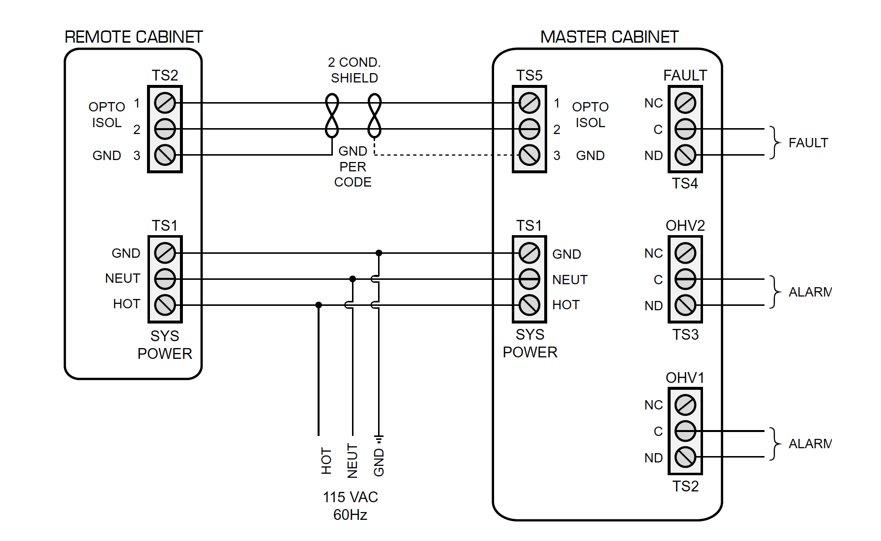
FIGURE 10: Z-Pattern® Typical Wiring
NOTES:
1.Remote reporting hardware and software supplied by others.
2.Remote – Master comm line (TS2 – TS5) is 2 conductor, 18 gauge, shielded, twisted pair.

FIGURE 11: Z-Pattern® Master Control Panel
